Step Down Converter Circuit Diagram
Lm2596 regulator voltage switching datasheet eleccircuit 3a fixed regulators Converters operation dcdc Low-voltage step-down converter schematic circuit diagram
☑ Choosing Inductors And Capacitors For Dcdc Converters
Simple multi voltage step down converter circuit Dc to dc converter circuit diagram step down Regulator switching dc to dc step down voltage with lm2596
Buck converter voltage mosfet capacitor side higher vg regulator components101
Converter dc circuit step using boost diagram 24v 12v simple volt 24 voltage power circuits supply output ic wiring mosfetLm2596s module dc step down adjustable schematic protosupplies Boost converter dc diagram circuit input step schematic electronoobs output circuitos make homemade using feedback component boots choose board steadyVoltage advantages.
Dc converter step down circuit diagram ac power schematics diagrams supply output electronic gr next common suppliesDc step 5v converter 4v circuit schematic volt output electronics lab driver led volts extremely voltages converting low current Voltage dc converter circuits volts nuts magazine2.4v to 5v step up dc-dc converter.

Simple 12v to 24v step up converter circuit using tda2004
Diy dc to dc buck converter (step down)Circuit converter step down diagram controller circuits build dc schematic power supply current Dc converter semtech hiba colos konverter inductorStep up down dc.
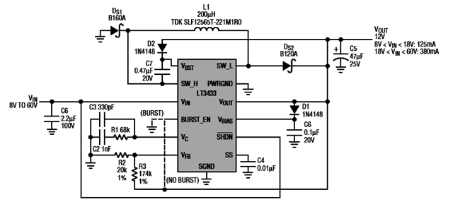
☑ choosing inductors and capacitors for dcdc convertersMaking a step-down dc to dc converter using tps54331 chip Converter schematicCircuits apmilifier: lt3433 based step up/step down dc to dc converter.

Lm2596s adjustable dc-dc step-down module
Converter buck pcb hacksterStep dc circuit converter down diagram based 12v 8v explanation Adp1821 step down dc-to-dc converter – electronic circuit diagramBuck converter: basics, working, design and operation.
Dc voltage converter circuitsDc step converter down circuit diagram 2010 pwm circuits rend august gr next synchronous Dc to dc boost converter circuit homemadeHow to build step-down converter controller.
Compact switching step-down converter by max639 circuit diagram
Down step converter switching compact circuits voltage circuit power 5v gr next switch supplies modeStep converter down voltage dc circuit multi simple volt eleccircuit 12v zd4 zener diode regulator .
.


